


Repair of the barrel
The inner surface hardness of the barrel is higher than that of the screw, and its damage comes later than that of the screw. The scrap of the barrel is the increase of the inner diameter due to time wear. Its repair method is as follows:
1, due to wear to increase the diameter of the barrel, if there is a certain nitriding layer, the barrel hole can be directly boring, grinding to a new diameter size, and then prepare a new screw according to this diameter.
2. The inner diameter of the barrel is machined and trimmed, and the alloy is cast again, the thickness is between 1~2mm, and then finished to the size.
3, under normal circumstances, the homogenization section of the barrel wear faster, this section (take 5~7D length) can be boring and trimmed, and then equipped with a nitriding alloy steel bushing, the diameter of the inner hole is referred to the diameter of the screw, left in the normal matching gap, processing and preparation.
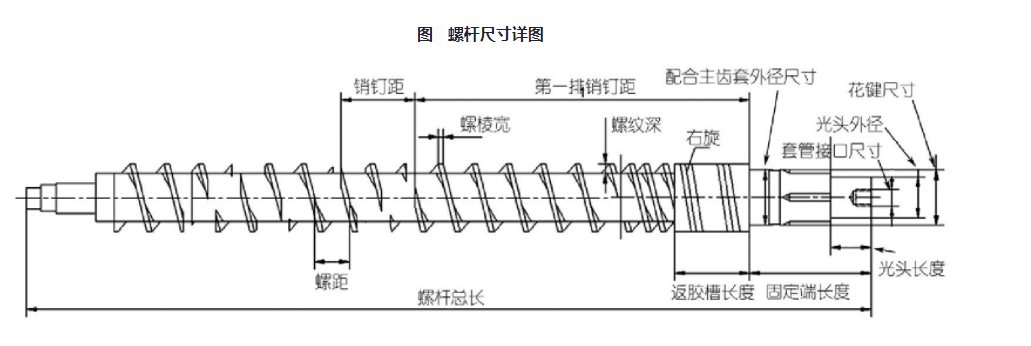
It is emphasized here that the two important parts of the screw and the barrel, one is a slender threaded rod, and the other is a small and long hole in diameter, their machining and heat treatment processes are more complex, and the guarantee of accuracy is more difficult. Therefore, whether to repair or replace the new parts after wear of these two parts must be comprehensively analyzed from an economic point of view. If the repair cost is lower than the cost of replacing the new screw, it is decided to repair, this is not necessarily the right choice, and the comparison between the repair cost and the renewal cost is only one aspect. In addition, it also depends on the ratio of the repair cost and the time of using the screw after repair to the renewal cost and the use time of updating the screw. It is the right choice to adopt the scheme with small ratio only economically.